Welcome to the installation guide for your new RailNET Automatic Equipment Identification (AEI) system. This article provides instructions to ensure a safe and efficient installation. Safety is paramount throughout this process. Railroad environments present unique hazards, and strict adherence to all safety protocols is mandatory. Precise workmanship is equally critical for the reliable operation of this AEI system. Carefully follow each step, double-check connections, and ensure all components are securely mounted. Your diligence in both safety and workmanship will guarantee a successful and long-lasting installation.
Read Instructions Thoroughly Before Beginning; Understanding all of the Steps will Help Avoid Difficult Situations
Scope of Supply
This installation package includes all necessary components for the complete installation of your RailNET Automatic Equipment Identification (AEI) system.
Provided Components:
RailNET assembly in NEMA Enclosure
Rohn towers for near and far side antennas with Ballast foundations
Conduit and Fittings for system connections
RFID Antennas
Frauscher Wheel detector and accessories
Traffic Loop presence circuit kit
Cellular Antenna
Tools and Materials Needed
Installer will be required to provide the following.
200lbs sack concrete (recommended)
Basic hand tools (imperial and metric)
Basic RF cabling tools
110V/1P/60Hz/15A Electrical Circuit and Associated Materials: The installation crew is responsible for providing and installing a dedicated 110V/1P/60Hz/15A electrical circuit, including all necessary wiring, conduit, breakers, and any other materials required to supply power to the AEI system.
Process Overview
Here's a general installation process overview for a RailNET AEI system, broken down into key stages:
Site Preparation and Planning:
Site Survey: Conduct a thorough site survey to determine optimal reader and antenna placement, identify potential obstructions, and assess power and cabling pathways.
Permitting and Approvals: Obtain all necessary permits and approvals from relevant authorities.
Safety Planning: Develop a detailed safety plan, including emergency response procedures as sites are often remote.
Material Acquisition: Gather all required materials, including those provided in the scope of supply and those the installer is responsible for (concrete, electrical supplies, tools, etc.).
Foundation and Conduit Installation
AEI Subsystem Assembly
Antenna Mounting and Hookup
Frauscher Wheel Transducer mount and Hookup
Loop installation
Cellular Antenna Installation
Electrical Installation:
Circuit Installation: Install the dedicated 110V/1P/60Hz/15A electrical circuit, adhering to all applicable electrical codes.
Install and connect system backup batteries.
Power Supply Connection: Connect the power supply unit to the electrical circuit and the reader unit.
Grounding: Ensure proper grounding of all electrical components. Bond towers to grounding rods.
System Configuration and Commissioning (Optimization)
Power-Up and Initial Checks: Power on the system and perform initial checks to verify proper operation.
System Configuration: Configure the AEI system according to the site-specific requirements.
Tag Testing: Perform tag testing to verify accurate tag reads and system performance.
Data Verification: Verify that the system is transmitting data correctly to the designated data collection system.
Final Inspection and Documentation:
Final Inspection: Conduct a thorough final inspection to ensure all components are properly installed and functioning.
Documentation: Complete all necessary documentation and optimization checklist.
Site Considerations
Site should be readily accessible to nearby roads to facilitate maintenance.
Site should be located near commercial power source.
Site should be located with consideration to the availability of appropriate communication facilities for system reporting and maintenance (cell coverage).
Site should be located to avoid discontinuities in the track structure (joints, switches, grade or rail crossings) in the immediate vicinity of the AEI system.
Site should provide sufficient space to install wayside equipment with respect to railroad clearance restriction requirements.
The site should be located in order to satisfy railroad application requirements and with a consideration of the communication and processing lead-time required by the user of the AEI data.
When feasible, multiple track locations should be located where track centers are greatest in order to locate antennas such that AEI tag read time is maximized. Where feasible, the number of tracks should be minimized.
High vandalism areas should be avoided.
Avoid low areas where flooding may occur.
Consideration should be given to consolidation with other types of railroad installations such as defect detectors.
Site selections should be made with an understanding of the railroad traffic patterns. Where feasible, site selection should avoid locations where stopping, reverse moves, doubling, or light engine movements occur frequently.
If feasible, sites should be located to avoid potential sources of interference including large metallic objects and obstructions in close proximity to the reading area, reflective surfaces, and high voltage power lines, and other fixed and portable AEI reader systems.
In order to reduce the potential for interference and subsequent performance degradation, site selection should be made to avoid having two AEI systems powered on at the same frequency at the same time. Two like frequencies should be kept a minimum of 1,500 Ft. apart. AEI transmitter frequencies are: 902.25 MHz, 903.75 MHz, 910.00 MHz, 911.50 MHz, 913.00 MHz, 915.00 MHz, 917.00 MHz, 918.50 MHz, 920.00 MHz, and 921.25 MHz
Pre-construction
Determine the transducer location first. This is the center of the site. The center of the transducer must be located between two ties. This allows for the transducer claw to clamp under the rail.
Mark the tower locations. Tower Foundations should be directly out from the transducer 12 feet 6 inches from center of track.
Before digging, contact a qualified utility locator service. Utilities need to be marked before digging to safely avoid them. See below a non-comprehensive list of utility locator services. Local authorities need to be notified before work begins.
Tower Foundations 400402 to be setback per layout, 12 foot 6 inches from center of track.
Tower top plates are to be flush with top of rail. A string and line level is the easiest way to determine this.
Both foundation "notches" toward the track(deviation in photo)
Holes dug so that foundations can be set at track level.
Foundations are designed to be set in ballast
Far-side (Non-Panel) foundation can be set in native backfill.
Near-side should be set in 200lbs sack concrete and covered in native backfill. In most cases, adding dry concrete is sufficient. No need to cure before completing installation.
Foundations to be set and backfilled after the conduit is in the trench
Foundations are to be hand backfilled and tamped checking and adjusting for square and level.A 10 foot tower is to be attached to these, small deviations from level are accentuated over the length of the tower.
Conduit
Install one run of conduit 400377 between the two foundations.
Conduit is provided in the kit
Self-Priming PVC cement is provided in the kit
Cut and glue pieces to put one conduit run between the Tower Foundations.
Conduit run to be 36 inched below top of rail to prevent damage from trains and maintenance equipment.
Conduit to be vertical on each end. (as shown)
Use supplied 90deg sweeps.
Leave several feet of conduit above top of Foundation (to be trimmed later)
Conduit Trench to be hand filled and tamped to avoid damage to the conduit.
Maintain the plumb nature of each end as backfill continues
Ground Rods
Ground Rod Placement
Driving the ground rods 400421 directly after back-fill before further assembly can help keep a clear workspace.
Drive one ground rod 6-12 inches from each foundation tower.
Ground Rods should be driven to 4-8" above grade
If you mushroom the head of the rod in the process, it will need to be ground back to profile in order to CADweld the bonding wire to it. (process later in the procedure)
Towers
Pinning Illustration
Install tower sections and tower caps.
Tower 400248 is manufactured with male/female ends. The male end will be up, the female end will fit over the pegs on the tower foundation.
Install tower caps 400530 on the male tower end prior to erecting the tower.
Fit the tower onto the foundation pegs.
Drill a 9/32" hole through the tower and peg.
Use provided bolts to pin the tower in place 3 times.
Far Side Junction Box
Unistrut to Tower Clamp
Once the towers are erected, the Far-side Junction box 400944 is installed:
This is the non-enclosure side of the system
Bolt Unistrut to the back of the junction box using provided hardware
Cut the 3-inch conduit off 10 inches above the foundation plate.
Glue a 3-inch PVC slip by thread adapter onto the end of the PVC Conduit.
The Junction Box should be mounted using the unistrut clamps (4) and 3" thread nut as shown in the photo.
Mounting of RailNET Nema Enclosure
The System is ready for the mounting of the RailNET NEMA Enclosure 400059.
The RailNET NEMA enclosure is heavy and awkward to handle. Plan your movements, this is a multiple person job.
The Enclosure is to be mounted to the Rohn tower with the multiple fitting openings near the track, and the single (power feed) away from the track.
Orientation Diagram
Two spacers are provided to support the enclosure during installation and help with vertical spacing on the tower. Place the spacers on the foundation plate to help hold the enclosure in place while the unistrut clamps (4) are tightened.
Unistrut to Tower ClampNEMA Enclosure resting on 4x4 spacers
Antenna Mounting
Antenna Clamp Configuration
Mounting hardware for the two ParaPanel Antennas 400942 is included in the Antenna boxes.
The vertical center of the Antenna should be 42 inches above top of rail, facing the track. If the tower foundations were set properly measurement can be taken from the top of foundation.
Note: Mounting hardware for the parapanel antenna is stainless steel. Caution should be taken to avoid thread galling. This includes thread lubrication (best case "anti-seize"), and careful handling.
Use the provided screws to attach "L" brackets to the back of the antenna (2).
Provided "V" block sits against the long "L" and the "U" bolt goes around the tower post. As shown.
Mount the Near-side antenna first. It should hang off the tower facing the track on the opposite pole as the RailNET enclosure.
Place the second antenna directly across from the first.
Near-Side Antenna Tower PlacementFar Side Antenna Alignment
Antenna Connections
The antennas are hooked up using coaxial cable and type "N" connections. Care and craftmanship are required to ensure good RF performance. Ensure that all connections are tightened firmly against their washers. Moisture ingress significantly degrades performance. Do not kink or smash coaxial cable. Heliax, 400263 is a stiff, high efficiency, conduit rated coaxial cable that will be used for the far-side antenna connection. It requires careful handling to avoid kinking or smashing.
Several flexible coaxial whips with pre crimped ends are used in this step. Pay attention to the length in each step to make sure you have proper lengths for the other connections.
(2) Heliax field installable terminator Type N Female 400261
One terminator is packed with the Junction Box materials, and one is in the box containing the antennas.
3" PVC Slip joint to 3" female thread adapter.
PVC cement (provided)3" to 1" Reducer
4-6 feet of carflex 1" metallic flexible conduit
(2) 1" carflex fittings
Electrical tape
Tools Needed (not provided)
Hacksaw or angle grinder with cutoff wheel
Coaxial Cable stripping tool
Coaxial cutting tool
Pipe wrench
Procedure
Cut the near-side conduit 4-6 inches above the tower foundation top plate.
Cement the 3" slip joint by 3" female thread adapter onto the end of the conduit.
Seat one carflex fitting into the 3" x 1" reducer. The reducer is tapered. the fitting needs to be in the "big" end. It can be difficult to see the taper. Use the PVC conduit end to find the taper direction if needed. The reducer will only screw in when engaging the smaller end.
Thread the reducer into the conduit end a turn or two without tightening.
Attach one end of the provided carflex to the fitting now attached to the conduit and route the conduit to one of the carflex fittings in the bottom of the NEMA enclosure.
Mark and cut the carflex. Complete the connections as a test fit, (do not tighten)
Completely remove the carflex and reducer from the conduit and enclosure. Remove the carflex from the reducer leaving the fitting in the reducer.
Untape the heliax coil and straighten the first 3-4 feet of cable. Bend 4-6 inches of cable back upon itself and tape it tight. This creates a blunt end that will not catch on PVC joints. Push the heliax cable through the conduit from near-side to far-side. The heliax should thread through easily. When you can see the cable in the far-side junction box, go to the far-side, and gently pull the cable out the front of the box and up another 8 to ten inches.
Return to the nearside. Thread the reducer over the remaining heliax cable down to the conduit. Tighten (apply a bit of PVC cement to the threads to seal)
Thread the prepared carflex length onto the heliax cable. Tighten the fitting to the reducer.
Thread the heliax cable into the NEMA enclosure until the carflex fits as planned and tighten to the box. Be carful to not damage the heliax in this process.
In the NEMA enclosure, cut the Heliax 12-14 inches into the box. Follow end prep guidlines and install the female N heliax end. Install Instructions
On the far side cut the heliax to end 4-6 inches above the bottom of the junction box. Follow end prep guidelines and install the female N heliax end Install Instructions
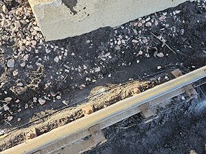
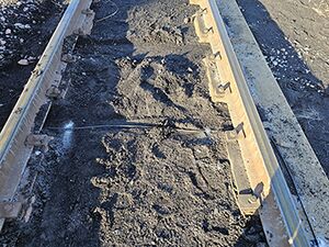
The mounting point on the track should be as close to in a line with the antennas as possible.
The Frauscher's protective hose should be cut to the appropriate length and then installed in the conduit fitting on the bottom of the NEMA enclosure. (As shown)
The sensor wire should be cut to length, (with a service loop) and landed in the enclosure as shown.
Presence Subsystem
Materials Needed
1Loop next to trackLoop running across, under track50-foot Bondstrand reinforced cable
Measure 20 feet up track and 20 feet down track. Mark the nearest tie in each location. This will be the extent of the presence detection loop.
Create a small trench by clearing ballast from the outside surface of the ties.
Uncoil the provided bondstrand and find the center.
Start on the far side of the track at least 4" from the tie plates. Put the center in line with the wheel transducer.
Lay the bondstrand down and secure to each tie using the nail down tie clips.
After clipping down 3-4 ties in both directions, lay out the rest of the loop. Pull through the trench you made in step 2.
Route back to the center.
Finish clipping down the cable on the far-side.
When you get to the point where the cable crosses the track, Route the cable down the side of the tie at least 4 inches then across the tie.
Clip across the vertical tie face 4 times.
Route back to tie top and clip the cable to the ties until they come together.
Double clip the cable as they come together.
Twist the cable together 5 twists for each foot between the track and the NEMA enclosure.
Cut the non-metallic conduit long enough to go from the NEMA enclosure to 1 foot from the rail.
Slip the conduit over the twisted cable.
Thread the cable through the fitting in the bottom of the NEMA enclosure, then secure the conduit in the fitting.
Cut, strip and land the loop cable in the terminals marked for the loop.
Fill in the trenches dug.
Cover the non-metallic conduit with ballast.
Cell Antenna
Install the cell antenna 400214 high on the tower, above the AEI box
4G LTE 50-ohm Omni Plus Antenna
Bracket that can connect antenna to tower is included
Rated wind velocity up to 130 mph
Rated Temperature limit -40 to 149 degrees
Electrical Connections
Grounding Connections
Materials Needed
No 6 bare copper wire
(2) cadweld mold ground rod to wire
(2) cadweld mold wire to tower.
Tools Needed
Wire cutter
cadweld sparker
Procedure
Weld wire to nearside tower. Use procedure As shown.
Weld wire to grounding rod. Use procedure. As shown.
Cut the copper wire on the excess side of the grounding rod.
Repeat for far-side tower
Wiring Power to the NEMA Enclosure
A certified electrician should wire the power to the NEMA Enclosure.
Power to the NEMA Enclosure should be run through the opening in the bottom of the enclosure. It is the single opening on the left side when looking at the box.
Power is wired into the 110v receptacle located on the left side.
NOTE: There is also an AC Transformer 400355 wired into the receptacle. Do not remove or alter this wiring.
Batteries
An area inside the NEMA enclosure has been marked for battery 400917 placement.
Install the batteries in the marked area.
Install the bonding bar between the two batteries.
Connect the batteries using the color codes (Black -)(Red +)
Heater
Final Connections
Plug the panel heater 400077 into the duplex outlet.
Turn the thermostat until the heater turns on. Once verified, return the thermostat to 40 degrees farenheit.
Plug the battery maintainer in to the duplex outlet.