
Upgrade AEI Site with Dedicated AI1200/AR2200 to MPRX
 |
| Figure 1 |
Transcore has sunset the AI1200/AR2200 RFID subsystem components utilized in Comet Electronics’ Railnet AEI system. Transcore has developed the MPRX, Multiprotocol Reader Extreme as replacement. The MPRX is a next-generation RFID reader that supports Association of American Railroads (AAR) formatted tags.
Comet Electronics has designed an interface card to make the MPRX seamless to the AI1200/AR2200 installation.
In a high speed site (up to 130 mph), installation will be similar to a dual AI1200/AR2200 installation (dedicated RF). It will use dual MPASS/MPRX, with connections to antenna port 0 on both units.
For detailed specifications of the MPRX, refer to Transcore’s document, 16-0079-001, MPRX User Guide.
Minimum AEI software version for standard multiplexed operation
5.1.1 B134
or
5.2.0.16
Materials Required:
Dual/Dedicated RF Site:
2 402173 MPRX, Multiprotocol RFID Reader
2 400183 MPASS Interface Card
2 402180 APU102 to MPRX Cable Assembly
4 400647 50Ω, 2W Dummy load (+2 reused from original installation)
Misc. Required:
- Laptop computer with serial port or USB to Serial adapter
- Communication program such as TeraTerm, HyperTerminal, etc.
- Null modem cable or modem cable with null adapter (25-pin DB male on APU-102 end)
- MPRX specific INI files (may be preloaded to APU102)
- Antistatic (ESD) wrist strap
- Pre-programmed Test tag mounted on backing plate.
Optional
- APU102 System Operations and Installation Manuals
- Communications program users guide
Upgrade Procedure
ATTENTION: |
The user is responsible for obtaining the appropriate radio transmitter license. In the United States, the authorized continuous wave (AAR-formatted operation) frequency band for this product is 902.25 to 903.75 MHz and 910.00 to 921.50 MHz. RF power output is rated for 2 watts. Users in all other countries should check with the appropriate authorities for licensing requirements. |
Determine RF frequency currently in use/licensed for site
If current license is for specific frequency, the MPRX can be set to the same frequency if in the currently allowable bands. Review your license documents or check the existing RF unit frequency. To view/verify the current frequency, examine the “toe-tag” or the printed label on the RF module (inside the enclosure). The Version 1 RF module will have the label on the right side. The Version 2 RF module will have a small label viewable through the Antenna one opening.
NOTE: |
Multiple RF sources in close proximity (< 1000’) must have minimum 1.5 MHz separation |
Files and Parameters Relative to the MPRX:
Steps 1-4 can be done remotely, prior to site visit.
- Connect the laptop to the APU102’s local port.
- Log into the APU102 to the Supervisory level (Change Prompt)
- Verify minimum software requirement (/ Slash command). Upgrade first if necessary.
- Verify if the MPRX files are preloaded
Enter the command: DIR MPRX*.*
01/12/2021 10:43 AM 278 MPRX9115.INI 01/12/2021 10:43 AM 278 MPRX9150.INI 01/12/2021 10:43 AM 278 MPRX9185.INI 01/12/2021 10:43 AM 302 MPRX9215.INI 01/12/2021 10:43 AM 26 MPRXMD0.INI 01/12/2021 10:43 AM 26 MPRXMD1.INI 01/12/2021 10:43 AM 32 MPRXMD2.INI 01/12/2021 10:43 AM 32 MPRXMD3.INI 01/12/2021 10:43 AM 34 MPRXMD4.INI 9 File(s) 1,286 bytes 0 Dir(s) 15,755,264 bytes free Sample Directory (there may be more frequency specific files loaded) |
- 5. If not present, upload the MPRX INI files using the 'ZREC' command
- 6. Enter the Parameter Editor (EP)
- 7. Navigate to appropriate parameters listed below and enter as necessary.
Ports.AVI1PORT.BaudRate=5
Ports.AVI2PORT.BaudRate=5
Acquisition.Reader1.PortFile=AVI1PORT.DAT
Acquisition.Reader1.IniFilename=MPRX****.INI
**** is desired frequency. File must be present on APU. Default for Reader 1 is MPRX9115.INI (911.5 MHz). See sample directory above.
Acquisition.Reader1.AntennaAssignment=2
(this should not change from current configuration)
2: Reader services both antennas (multiplexed-one on each side of track)
Acquisition.Reader1.Ant0PassiveLobe=16
Field measurement required. Will be determined after installation is complete.
Acquisition.Reader1.Ant1PassiveLobe=16
Field measurement required. Will be determined after installation is complete.
**** Other frequencies are available and may require additional INI files to be loaded.
Exit the parameter editor and log off of the APU102.
Install the MPASS Card
- Open the lid of the APU102 and power it off.
- Put ESD wrist strap on wrist and connect to ground lug on outside-bottom of APU102.
- Loosen the screws on the reader board card cage retainer. DO NOT REMOVE SCREWS.
- Slide the retainer down.
- Remove the cables from the AI1200 Reader card.
- Remove the AI1200 Reader card from the reader card cage.
- Install the MPASS interface card in the reader card cage.
- Connect the cables to the MPASS card, edge position.
- Slide retainer up and secure.
Install the first MPRX
- Remove the umbilical cable between the APU102 RF1 and AR2200 RF Unit.
- Label the antenna connection on the coax cable connecting to the AR2200 RF Unit.
- Remove the coax cable.
- If installed, remove the checktag cable from the RF unit.
- Remove the ground connection on the RF unit.
- Remove the RF Unit from the wall.
- Mount the MPRX in place of the RF unit. It may be necessary to relocate other components, wiring channels, etc.
- Connect the ground cable to the MPRX.
- Examine the MPRX end of the umbilical cables if not labeled. One connector has pin contacts, one has socket contacts. Connect the one with pins to the Sense port and the one with sockets to the Host Port. The connectors are keyed and require minimal effort to fully seat. Align the “arrows” of the connectors as shown in Figure 2, carefully insert connector and turn the knurled collar clockwise to seat completely (several revolutions).
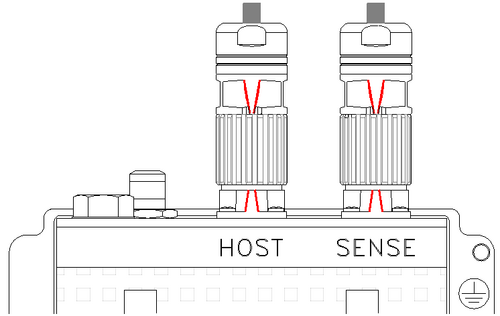
Figure 2 - If existing site used checktag, connect the checktag connector to the one extending from the Sense connector.
- Connect the CPC16 connector to the APU102, RF1 connection.
- Connect the coax cable to the MPRX antenna port 0.
- Install dummy loads on all unused antenna ports (reuse 1 from original RF unit).

Install the second MPRX
- Remove the umbilical cable between the APU102 RF2 and 2nd AR2200 RF Unit.
- Label the antenna connection on the coax cable connecting to the AR2200 RF Unit.
- Remove the coax cable.
- If installed, remove the checktag cable from the RF unit.
- Remove the ground connection on the RF unit.
- Remove the RF Unit from the wall.
- Mount the MPRX in place of the RF unit. It may be necessary to relocate other components, wiring channels, etc.
- Connect the ground cable to the MPRX
- Examine the MPRX end of the umbilical cables if not labeled. One connector has pin contacts, one has socket contacts. Connect the one with pins to the Sense port and the one with sockets to the Host Port. Align the “arrows” of the connectors as shown in Figure 2, carefully insert connector and turn the knurled collar clockwise to seat completely (several revolutions)
- If existing site used checktag, connect the checktag connector to the one extending from the Sense connector.
- On the second MPRX, connect its CPC16 connector to the APU102, RF2 connection.
- Connect the coax cable from second RF unit, antenna 1 to the 2nd MPRX antenna port 0 (zero).
- Install dummy loads on all unused antenna ports (reuse 1 from original RF unit).
Initialize the MPRXs
- Power on the APU102.
- Set/Verify power supply output to Reader(s) is 13VDC.
- Log onto the APU102 supervisory level (Change Prompt)
- Initialize all MPRXs with IR,* command. The APU will reply with initialization status.
Reader #0 initialization complete.
Reader #1 is not in current configuration.
Reader #2 is not in current configuration.
Sample Reader initialization reply (single MPRX installation)
- If a failure is indicated, verify the files are present as in Files and Parameters Relative to the MPRX, step 4 and parameters are correct as in Files and Parameters Relative to the MPRX, step 7. Verify boards are installed and everything is cabled correctly. Verify Reader power is present. Correct as necessary (reboot required for changes to Ports.AVx1PORT.BaudRate) and reinitialize the MPRXs.
Optimization Checks
RF power checks and Checktag operations can be run if desired. Wattmeter connections and command sequences are the same as the AI1200/AR2200 configuration.
Measuring the Horizontal Read Lobe (Window)
- Set the Sonalert selector switch on the interconnect board in the bottom of the APU102 to the left.
- Activate the MPRX with the command RFON,0,*
- Measure the horizontal read window for antenna 0.
At the edge of tie facing antenna 0 (typically the hut side of the track), hold the test tag horizontally at 42” above top of rail. You should hear the Sonalert chatter (not a solid tone). Keeping the tag steady, move slowly to the right until the sonalert tone stops. Mark this position on the tie. Now, move to the left, holding the tag as before. The Sonalert will sound again. Continue moving until it stops. Mark this position on the tie. Measure and record the distance between the marks (Round up to next foot). This value will be entered into Acquisition.Reader1.Ant0PassiveLobe.
- Measure the horizontal read window for antenna 1.
Face antenna 1 and repeat measurement as above. Its value will be recorded in Acquisition.Reader1.Ant1PassiveLobe. Press <ENTER> to cancel the RFON command.
- Enter read lobe parameters in the parameter editor if changed from original values.
- Perform a fast reboot with R,F command and confirm so changes will take effect.
- Set the Sonalert selector switch to the center position (off).
Housekeeping
Optional (5.2 AEI Software only)-Use the NOTE command to add a login notice regarding the MPRX installation.
e.g., NOTE A MPRX installed, 04/15/2021 09:30
NOTE L
Perform the parameter backup (BP)
Recommended: Update the mirror image (SHELL IBACKUP and Full reboot)
Correct any site deficiencies.
Comet Electronics Service technicians are available M-F, 8:00 am to 4:00 pm Central Time if you require assistance or additional documentation.
(888) 700-4214 or (816) 245-5400
OR
e-mail to support@cometind.com