
TDA-205 Installation and Optimization to MicroHBD
The following details installation and optimization of the TDA205 to utilize Frauscher RSR110-002, single segment wheel detector(s) to wayside equipment, such as HBD, HWD, or other defect detectors. The actual detector is housed in the SYS1 side of the sensor housing. Optionally, some customers may choose to use the dual segment Frauscher, RSR110-001 for these installations. Setup (using SYS1) is the same for either.
If needing installation for routing on APU-102, refer to TDA205 Installation and Optimization for Routing on APU-102.
Conventions:
- Detector, sensor and transducer are interchangeable terms referring to the Frauscher RSR110-002
- “A” segment referenced is typically the left sensor, “B” segment is typically the right sensor.
Tools Required:
- Misc. small hand tools.
- Small flat blade screwdriver
- Wire cutters
- Wire strippers
Documents Required:
- Drawing 70-0180-04/05, Wayside Detector with Frauscher Wheel Detectors and TDA205
- Frauscher Wheel Detector Installation and Optimization
- Frauscher Wheel Detector Installation on Dual Sensor Mounting Bracket
Installation of the TDA205
If necessary, install the Frauscher RSR110-002, wheel detector(s). Refer to sections 1 and 2 of the Frauscher Wheel Detector Installation and Optimization document, 376-0047-00 or Frauscher Wheel Detector Installation on Dual Sensor Mounting Bracket document, 376-0047-01. The documents may refer to a dual segment sensor (RSR110-001), however, physical installation is the same.
TDA205 Installation
Refer to Drawing 70-0180-04/05 as needed when following the steps below. Note that color codes shown are typical and may vary. Substitute accordingly.
- 1. Mount the TDA205 on the wall near the wheel detector/sensor input of your trackside device.
- 2. When wiring the TDA205 to the sensor, keep the following points in mind:
Required! |
Reliable connections at splice box and protection panel are IMPERATIVE for correct operation of wheel detectors. |
- 3. Refer to your particular site drawing when checking hut wiring as there may be a change in color designation.
- 4. If the wheel detector splice is in an underground splice box, the splice must be soldered and waterproofed. If ring terminals are used in a weatherproof junction box, verify crimps are secure and proper terminals are being used with sensor lead and shielded pair cable to surge protection panel.
- 5. If connected, disconnect the DC power cable from the TDA205. DO NOT reconnect to TDA205 until fully wired. Connect the DC power cable to the hut DC distribution point. Input voltage range from +9 to +36 VDC.
- 6. Connect the wheel detector wiring from the surge protection panel to the TDA205 Sensor Inputs as shown in drawing 70-0180-04/05.
- 7. Connect the TDA205 Sensor Outputs to the wheel detector inputs of your Wayside detector as shown in drawing 70-0180-04/05.
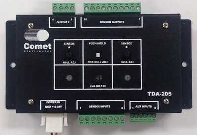
Figure 1: TDA205 case

Frauscher Wheel Detector Optimization
This chapter provides instructions on optimizing the axle acquisition side of the system with the Frauscher wheel detector and the TDA205 wheel detector interface. Refer to Figure 1 for TDA205 user controls.
Frauscher Wheel Detector Calibration
1. Before connecting power to the TDA205 voltages, check the DC voltage supplied to the TDA205’s power cable. Input voltage can range from +9 to +36 VDC, but is typically either +12 or +24 VDC. Verify polarity is correct.
2. Connect the DC power to the TDA205.
3. On the TDA205, press and hold the “NULL” button. With the “NULL” potentiometer above each sensor’s 2-color LED, adjust until the LED is extinguished. The following table indicates which direction to turn the null potentiometer:
To Turn LED Off | |
Sensor A or B Red LED is lit |
Counterclockwise |
Sensor A or B Green is lit |
Clockwise |
4. Release the “NULL’ button.
5. Press and release the “SENSOR CALIBRATE” button. The Sensor LEDs may light and the CALIBRATE LED will blink during the calibration process. When calibration is done, the Calibrate LED will light solid and Sensor LEDs will extinguish.
6.Repeat the null process in step 3.
Wheel Detector Testing
Before testing the wheel detector, make sure you have performed the adjustments phase of this procedure.
Sensor Voltages (Sensor Input)
Voltage across either sensor segment should be approximately 8.75VDC ± 0.25 V with no wheel or metal over the sensor. “A” segment voltage may be measured at Sensor Input pin 1 (+) and pin 2 (-). “B” segment voltage is measured at Sensor Input pin 5 (+) and pin 6 (-). The segments are 2 separate circuits within the sensor (or separate sensors depending on installation) and the voltages will not match between “A” and “B” but should be close. Placing a piece of metal over a sensor segment causes the corresponding segment input voltage to rise to approximately 10 VDC ± 0.5 VDC. (This voltage varies depending on the size and placement of metal over sensor segment.)
TDA205 Output Voltages
TDA205 voltages may be measured at the TDA205 Sensor Output connector or the Wayside Detector’s wheel detector inputs. For procedure clarity, voltages at the TDA205 will be listed; however, it is recommended that the voltages also be checked at the Wayside Detector’s wheel detector inputs to verify proper wiring.
- Confirm no metal is present over the sensor. Voltage should measure 0.0 VDC ±0.1 VDC.
- Place a piece of metal over each sensor segment, check voltage of the “A” sensor at Sensor Output pin 1 (+) and Sensor Output pin 2 (-), then check the “B” sensor voltage at Sensor Output pin 6 (+), Sensor Output pin 7 (-). Voltage across each segment should rise significantly. The actual voltage level will depend on front end loading of the Wayside Detector’s input circuitry.
Indicator Test Method
With the Frauscher and TDA205 connected as in drawing 70-0180-04/05, confirm proper adjustment using the following steps:
- Before testing the wheel detector, make sure you have performed the adjustments phase of this procedure.
- Lay a piece of metal on the “A” sensor. The A LED on the TDA205 should light GREEN. The appropriate input indicator of the Wayside Detector should show activity.
- Remove the metal from the “A” sensor. The LED on the TDA205 should go off and the Wayside Detector should show inactive/idle. You may need to wait for the Wayside Detector to timeout before proceeding.
- Lay a piece of metal on the “B” sensor. The B LED on the TDA205 should light GREEN. The appropriate input indicator of the Wayside Detector should show activity.
- Remove the metal from the “B” sensor. The LED on the TDA205 should go off and the Wayside Detector should show inactive/idle. You may need to wait for the Wayside Detector to timeout before proceeding.
The site is now ready for evaluation of axle information using actual trains.