
Appendix F - Specifications
APU-102 Internal Components Specifications
Inside the Card Cage
L-Series (LX-800) APU-102
The following cards are pre-installed inside the APU-102 card cage:
- LX-800 “Geode” Processor Card
- TDA-104 Card
- DT4070 Series Modem Card
- COM4N Card or LX-COM (Quad serial board-daughtercard on LX-800)
Specific card information and drawings may be found later in this section.
PN-Series (Pentium with network option) APU-102
The following cards are pre-installed inside the APU-102 card cage:
- LPM-TX Pentium Card
- PPM-10/100, PC104, Network Interface Card (daughtercard on Pentium)
- PCM-CFLASH2, PC104 Compact Flash Adapter (daughtercard on Pentium)
- PCM-SSD Card, PC104 Solid State Disk (daughtercard on Pentium)
- TDA-104 Card
- DT4070 Series Modem Card
- COM4N Card
Specific card information and drawings may be found later in this section.
P-Series (Pentium) APU-102
The following cards are pre-installed inside the APU-102 card cage:
- LPM-TX Pentium Card
- PCM-SSD Card, PC104 Solid State Disk (daughtercard on Pentium)
- TDA-104 Card
- DT4070 Series Modem Card
- COM4A Card
Specific card information and drawings may be found later in this section.
E-Series (486) APU-102
The following cards are pre-installed inside the APU-102 card cage:
- 486 Card
- TDA-104 Card
- DT4070 Series Modem Card
- COM4 or COM4A Card
- USSD Card
Specific card information and drawings may be found later in this section.\
LX-800 Card Layout (Front) / L-Series APU
Card Layout

Jumper Settings
J13 |
3-4? |
J23 |
11-12 |
NOTE: Onboard Battery jumper, J31, is shipped disabled and needs to be enabled before use (1-2). If external battery is used, the onboard battery needs to be disabled (OPEN).
LX-800 Card Layout (Back) / L-Series APU
Card Layout

Jumper Settings
NOTE: All license stickers MUST be applied to be in compliance with all applicable software licenses.
LPM-TX Pentium Card / P-Series and PN-Series APU
Layout
NOTE TO EDITORS: The image is not displayed in Word or PDF sources.
Jumper Configurations
J8 OPEN
J9 OPEN
J10 OPEN
J11 1-2
J12 OPEN
J13 2-3
J14 2-3
J15 2-3
J19 1-4*
2-15*
3-12*
5-6
7-22*
9-10
11-14*
17-24*
J20 1-2
J21 1-2
J22 2-3
J23 OPEN
J24 3-5
4-6
*Wire wrap jumpers
SSD removed for clarity
PPM-10/100 Network Interface Card / PN-Series APU
Layout

Jumper Configurations
JP5 1-2
3-4
PCM-CFLASH2 PC104 Compact Flash Adapter / PN-Series APU
Layout
![thumb]left](/index.php/File:F16_PCM-CFLASH2_PC104_Compact_Flash_Adapter_PN-Series_APU.png)
Jumper Configurations
JP5 2-3
JP10 1-2
PCM-SSD Card / P-Series and PN-Series APU
Layout

Jumper Configurations
JP1 1-3
2-4
5-7
9-10
JP2 1-2
JP3, JP5, JP7 configured as follows:
1-2
3-5
4-6
7-8
9-10
JP4, 6, 8 configured as follows:
2-3
JP9 1-2
JP10 1-2
JP11 1-2
3-4
5-6
7-8
JP12 1-2
3-4
5-6
486SLC Card Layout / E-Series APU
Card Layout
NOTE TO EDITORS: The image is not displayed in Word or PDF sources.
Jumper Settings
|
- Wire wrap jumpers
TDA-104 Card Layout / Any Series APU
==
Card Layout ==== NOTE TO EDITORS: The image is not displayed in Word or PDF sources.
==
Jumper Settings ====
J1 |
OPEN (50-pin connector) |
J2 |
OPEN (10-pin connector) |
J3 |
2-3 (Depends on site.) |
J4 |
1-2 TOP |
3-4 SECOND FROM TOP | |
(5-6,7-8 OPEN) BOTTOM TWO | |
J5 |
1-2 (May be out depending on mod. Remove if diode above is shorted.) |
J6 |
OPEN |
J7 |
ALL JUMPERED |
J8 |
1-2 (May be out depending on mod. Remove if diode above is shorted.) |
J9/J10 |
ALL OPEN |
J11 |
ALL OPEN |
DT4070-33/DT4070-56 FAX/Modem Card Layout / Any Series APU
Card Layout

Jumper Settings
JP2-A |
OUT |
JP2-B |
OUT |
JP3 |
IN |
JP4* |
E IN ONLY!!! |
JP5 |
OUT |
JP6 |
OUT (install jumper if ground strap not used) |
JP7 |
OUT |
JP8 |
OUT |
NOTE: JP6 must be IN if ground strap is not attached to the modem and chassis ground.
DT4070-56 FAX/Modem Ver. 2 Card Layout / Any Series APU
Card Layout

Jumper Settings
No jumpers except for optional chassis ground
NOTE: JP1 must be IN if ground strap is not attached to the modem and chassis ground.
LX-COM Quad Serial Board / L-Series APU
Layout

Jumper Settings
Verify internal battery, Jumper J31 on LX-800 board is disabled (Open). Connect External Battery at J9 before use.
COM4(A) Card Layout (Non-Network) / E-Series and P-Series APU
L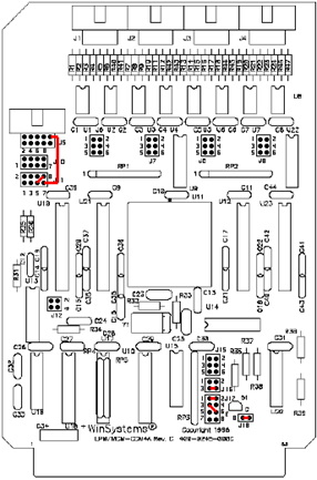 ayout
ayout

Jumper Settings
J1, J2, J3, J4, J5 |
External connections |
J6, J7, J8, J9, J10 |
OPEN |
J11 |
5-8 (Wire-wrap wire) |
J11, pin 7 |
J5, pin 9* |
J12 |
OPEN |
J13 (Rev “A” boards) |
1-2 |
3-4 | |
J14 (Rev “A” boards) |
1-2 |
3-4 | |
J15 |
OPEN |
J16 |
3-4 |
J17 |
1-2 |
3-6 (Wire-wrap wire) | |
J18 |
1-2 |
* Wire-wrap from J11, pin 7 to J5, pin 9. Rev “C” boards have 2 eyelets to left of J11 that provide same connection.
COM4N Card Layout (Network) / L-Series and PN-Series APU
Layout

Jumper Settings
|