Welcome to the installation guide for your new SensorLink system. This article provides instructions to ensure a safe and efficient installation. Safety is paramount throughout this process. Railroad environments present unique hazards, and strict adherence to all safety protocols is mandatory. Precise workmanship is equally critical for the reliable operation of this SensorLink system. Carefully follow each step, double-check connections, and ensure all components are securely mounted. Your diligence in both safety and workmanship will guarantee a successful and long-lasting installation.
Read Instructions Thoroughly Before Beginning; Understanding all of the Steps will Help Avoid Difficult Situations
Scope of Supply
The installation package includes all necessary components for the complete installation of your SensorLink system.
Inside the SensorLink NEMA Enclosure
Provided Components:
NEMA Enclosure, which houses the SensorLink System
SensorLink Processor
MPRX
Surge Suppression
Cellular Modem
Cellular antenna (mounted on top of enclosure)
Battery Charger
Sodium Ion Battery
Two 4" x 4", 10-foot Galvanized Metal Posts
Cables, Conduit and Fittings for system connections
Two RFID Antennas
Frauscher Wheel detector and accessories
Radar Presence kit
Tools and Materials Needed
Installation also requires:
Basic hand tools
Drill driver with Phillips and star bits
Pickaxe
Two-person auger, with a bit that is 8" in diameter and 36" long
250 lbs dry concrete
5 gallons of water
Two magnetic levels
Block-and-tackle rig (recommended)
6-foot ladder
Process Overview
The following is a general installation process overview for a SensorLink system, broken down into key stages:
Site Preparation and Planning:
Site Survey: Conduct a thorough site survey to determine optimal reader and antenna placement. Identify potential obstructions and assess cabling pathways. If the site is to be served by an electrical circuit, check for access to power.
Permitting and Approvals: Obtain all necessary permits and approvals from relevant authorities.
Safety Planning: Develop a detailed safety plan, including emergency response procedures, as sites are often remote.
Material Acquisition: Gather all required materials.
Post and Ground Rod Installation
SensorLink Subsystems
Battery connections
System Configuration and Commissioning (Optimization)
Power-Up and Initial Checks: Power on the system and perform initial checks to verify proper operation.
Tag Testing: Perform tag testing to verify accurate tag reads and system performance.
Data Verification: Verify that the system is transmitting data correctly to the designated data collection system.
Final Inspection and Documentation:
Final Inspection: Conduct a thorough final inspection to ensure all components are properly installed and functioning.
Documentation: Complete all necessary documentation and optimization checklist.
Site Considerations
Site should be readily accessible to nearby roads to facilitate maintenance.
Site should be located where ample sunshine is available (NOT necessary for electric installations).
Site should be located near commercial power source (NOT necessary for solar installations).
Site should be located with consideration to the availability of appropriate communication facilities for system reporting and maintenance (cell coverage).
Site should be located to avoid discontinuities in the track structure (joints, switches, grade or rail crossings) in the immediate vicinity of the SensorLink system.
Site should provide sufficient space to install wayside equipment with respect to railroad clearance restriction requirements.
The site should be located in order to satisfy railroad application requirements and with a consideration of the communication and processing lead-time required by the user of the data.
High vandalism areas should be avoided.
Avoid low areas where flooding may occur.
Site selections should be made with an understanding of the railroad traffic patterns.
If feasible, sites should be located to avoid potential sources of interference including large metallic objects and obstructions in close proximity to the reading area, reflective surfaces, and high voltage power lines, and other fixed and portable AEI reader systems.
In order to reduce the potential for interference and subsequent performance degradation, site selection should be made to avoid having two AEI systems powered on at the same frequency at the same time. Two like frequencies should be kept a minimum of 1,500 Ft. apart. AEI transmitter frequencies are: 902.25 MHz, 903.75 MHz, 910.00 MHz, 911.50 MHz, 913.00 MHz, 915.00 MHz, 917.00 MHz, 918.50 MHz, 920.00 MHz, and 921.25 MHz
Pre-construction
Determine the transducer location first. This is the center of the site. The center of the transducer must be located between two ties. This allows for the transducer claw to clamp under the rail.
Mark the 4" x 4" post locations. Posts should be directly out from the transducer -- 12 feet, 6 inches from center of track.
Before digging, contact a qualified utility locator service. Utilities need to be marked before digging to safely avoid them. See below a non-comprehensive list of utility locator services. Local authorities need to be notified before work begins.
Comet Industries is not affiliated with or endorsed by any of the service providers listed.
Earthwork
Two 4" x 4" galvanized posts and the 1" Sealtight conduit (with the far-side antenna cable inside) need to be installed below grade.
Post holes
Holes should be located across from one another, each of them 12 feet, six inches from the center of track.
Holes should be aligned with wheel sensor (transducer)
Holes must be 8 inches in diameter and 3 feet deep.
Shallow Trench
One 3"-deep conduit channel is needed between the two post holes.
Use the pickaxe to dig out a small trench from the base of the far-side antenna, under the track, and out the other side to connect with the Enclosure
Step-by-Step Installation Guide
Unpack
Carefully disassemble wooden shipping crate, removing lid first.
Take out any boxes or items packed inside the crate that are not attached to the NEMA Enclosure. Set those aside.
Clip bands on palleted items, providing easy access as needed.
Locate and Dig Post Holes
An auger helps with the post hole digging, but it is still a difficult job.
Measure 12 feet, six inches from the center of the track for a spot that lines up between two railroad ties (the wheel sensor will be installed between the ties later).
Mark the location with marking paint or in some other fashion.
Directly across from that location, measure 12 feet, six inches from the center of the track. Mark that location, as well.
Dig the holes for the 4”x 4” mounting posts at the marked locations.
COMET recommends that two people use a gas-powered auger with a bit that is at least 36” long and 8” in diameter.
Dig the two holes 36” deep at the marked locations on both sides of the track.
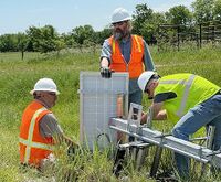
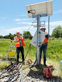
HINT:Breaking up the top few inches of soil and rocks with a pickaxe will allow the auger to penetrate the crust Attaching solar panel; note pole is supported on an aluminum ladder laid on its side.easier.
Attach Solar Panel to Top of Near-Side Pole
At this point, COMET suggests attaching the solar panel to the top of the near-side pole while the top end is still easily accessible. This requires, however, that the panel end of the pole be supported so that the panel does not rest on the ground. When attaching the solar panel to the near-side pole, remember it will need to face South or Southeast (preferably South) once the pole is erected. "The Enclosure faces away from the track; and the solar panel faces South." Keep this description in mind when determining which way to attach the panel to the pole.
Erecting Poles
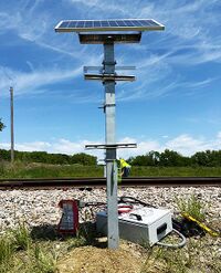
Place the pole with the solar panel in the near-side hole. The side of the pole with the brackets for the Enclosure should face away from the track, the solar panel should face South as much as possible, and the pole must be square to the track.
Fill the hole around the centered pole with the dry concrete, packing it firmly as it fills.
(Optional) Pouring a small amount of water in the hole at two or three levels as the hole is filled can be helpful.
It will take about 2.5 50-pound bags to fill one hole.
Keep the pole square to the track.
Using two magnetic levels, keep the pole level both vertically and horizontally.
Follow above instructions to erect far-side hole.
Near-side post erected.
Far-Side Antenna Cable
Lay out the far-side antenna cable. Starting at the near-side pole, use the shallow trench to lay the antenna cable under the track and to the bottom of the far-side pole. Pull through enough cable to reach up to the antenna connector.
Coil any extra cable and lean it neatly against the near-side pole
The mounting point on the track should be in line with the poles as much as possible and between two ties.
Mounting the NEMA Enclosure
Take the Enclosure to the near-side pole, on the side away from the track, and prepare to install it.
Unwind the cables coming out of the bottom of the enclosure and spread them out and away from the track so that they won’t be in the way for installation.
NOTE: At this point, COMET suggests you use a simple block-and-tackle rig to help lift the Enclosure and hold it in place while connecting to brackets. Doing so will make the following steps of the process much easier.The easiest way to raise the NEMA box into position is with a block-and-tackle setup
Connect one end of the block-and-tackle to the top of the pole and the other end to one of the two holes near the top of the box on the back side.
Raise the Enclosure. It will rise at an angle, which is fine.
When it is at the right height, secure the rope to hold the Enclosure in place.
Connect the top bolt opposite the hook first. Do not tighten any of the bolts until all four have been started.
Remove the hook and connect the other bolt near the top of the box.
Then connect the bottom bolts.
When all bolts have been started, go back and tighten bolts
Adjust bracket as necessary.
Attach Antennas
Far side Antenna
Backside of antenna, showing bracket and cable connections
Make sure antennas are installed right-side up. The brand name of the antenna goes at the top, right-side up.
Connect the antennas to their brackets with four bolts Note: Mounting hardware for the parapanel antenna is stainless steel. Caution should be taken to avoid thread galling. This includes thread lubrication (best case "anti-seize"), and careful handling.
Vertical center of the antenna should be 42” above the top of rail
Adjust bracket as necessary
Antennas should be at the same height, facing the track and each other.
Connect Cables to Antennas
For the far-side antenna, run the cable in the trench under the track and to the other side.
Leaving enough cable to reach above to the antenna connection on the far-side pole, loop any extra cable from both sides and lay it neatly against the near-side post
On both sides of the track, attach the cables and hoods to the antennas
Attach the Radar
inside radar boxRadar connection from below
Attach the radar box to its bracket on the pole
A wire lead will be used to feed the gray radar cable up through the cable conduit on the post and out the hole midway up the conduit.
Push the 30-inch, 14-gauge aluminum wire (included in hardware box) through the hole midway up the pipe and push it out the bottom of the conduit. Attach the wire to the radar cable and use it as a lead to pull the radar cable up the conduit and out the hole.
Connect the cable inside the Radar box. Then close and latch the box, sealing it as tightly as possible.
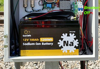
NOTE: Before completing the next set of instructions, MAKE SURE THE BREAKER IS OFF in the Enclosure
Battery and breaker location
Install Battery
Put the battery in the bottom of the Enclosure and connect the battery cables to it.
Make sure Positive cable goes to the POSITIVE pole; make sure Negative cable goes to NEGATIVE pole.
Connect the Solar Panel
Take the red and black wires from under the Enclosure and feed them up the cable conduit.
Connect them with the panel: positive to positive; negative to negative.
Make sure they click firmly in place with the cable connectors.
Ground Rods
Drive in the ground rods. Driving them near the post, where the ground has already been disturbed is easiest.
If you mushroom the head of the rod during installation, it will need to be ground back to profile in order to CAD weld the bonding wire to it.
Drive one ground rod 2" - 6" from each post.
Ground Rods should be driven to 4" - 8" above grade
Connect the copper wire [XXXXXneed clearer directions]
Finishing Up
Put the End Caps on the Posts
Push the plastic, 4” x 4” caps into the ends of both poles
XXX[Need startup instructions, final check up, etc.XXX]